
Instruction Manual for Water Brake-Type Absorption Dynamometer
The power absorbed by the Hydra-Brake® is due to a combination of shearing and pumping action and acceleration and deceleration of the water as it is thrown from the holes in the rotors to the holes in the stators in passing through the brake. The major part of the absorption is due to the acceleration and deceleration action.
For any given speed, the power absorbed by the brake may be increased or decreased by increasing or decreasing the depth of immersion of the rotors in the water. At any given speed, the power absorption can be varied from the maximum to about 2% of maximum under ideal conditions using a continuous flow system. Our normal recommendation is to restrict the operation of the brake between 10% and 100% of maximum absorption capacity. However, as the skill of the operator increases, operation under 10% of maximum can be realized if proper valves and controls are used. See schematic of control systems for typical installation.
A summary of requirements for good control on continuous flow systems follows:
- Properly sized brake
- Constant pressure water supply source
- Properly sized inlet and discharge valves. Use V-ported (or equivalent) valves, which have no movement of plug with respect to seat once set in a given position.
- Atmospheric vent for water compartment
- Atmospheric drain on discharge of brake
- The discharge line should be run downhill from the brake and contain no U-bends or traps
- Good speed control on the prime mover
In general, the Hydra-Brakes® are provided with ball bearings with provisions for oil or grease lubrication. Where space is limited, and speeds are not excessive, grease-packed cartridge bearings may be used. (Special small, grease packed cartridge bearings are being used at speeds of up to 26,000 rpm, but they require more frequent attention.)
Brakes are provided with 1/8″ NPT for installation of spring-loaded thermocouples for measuring bearing temperatures. Thermocouples and temperature indicators are optional and can be supplied at extra cost.
The power absorbed by the Hydra-Brake® may be measured by two basic methods. The first method is to measure heat rejection to the water by using the water flow and temperature rise through the brake. This method is used for direct mounted (uncradled) units where accuracies in the order of 2% are satisfactory. The second and more accurate method is the conventional method for measuring torque and speed. In this case, the brake is mounted on trunnion bearings, and an arm is provided for measuring torque. The cradle for this brake may be of the cantilever type. The torque may be measured by using a weight scale, dead weights, or by load cell of the pneumatic, hydraulic, or strain gage type. The selection depends on the preference of the user. Instrumentation should be selected for the degree of accuracy required.
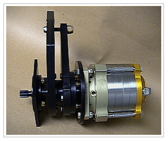
A third method of the cantilever type which is gaining acceptance where space is limited is the use of a special torque-measuring device installed between the brake and the prime mover. This unit consists essentially of a series of axial beams instrumented with strain gages. Flanges are attached on both ends of these beams, one for mounting onto the prime mover and the other end to support the brake. The signal for the strain gages is fed into an instrument which is calibrated to read torque.
The materials generally used in the construction of the brake are:
- Aluminum (forged) end flanges–anodized.
- Alloy steel (SAE 3312 or equal ) shaft, chrome, or CAD plated over areas exposed to water
Casing, rotors, and stators are made of aluminum when light weight is important, or stainless steel, which costs and weighs more but is superior to aluminum for its wear and anticorrosion properties.
Most models are furnished with a splined brake shaft for ease of mounting and to permit some misalignment. A splined adapter shaft is used between the prime mover and the Hydra-Brake® shaft.
There are two general systems used for supplying water to the brakes. The first and most widely used is the continuous flow system described in detail below. This system is satisfactory for testing turbines and gearboxes. The other is the closed loop system with heat exchangers.
In order to ensure proper operation of the Hydra-Brake®, a constant pressure supply source must be used. Some methods for obtaining this supply follows:
- A simple method is to use an open tank mounted at sufficient height to provide ample pressure to the brake. A liquid level control and an overflow pipe should be incorporated in this tank.
- When sufficient height is not available a centrifugal pump may be used to supply the brake. The pump suction line should be immersed in the tank or reservoir of constant level. An air chamber should be used on the discharge line as close as possible to the pump.
- A pressure-regulating valve which is fed from a high-pressure system may be used to supply water to the brake at reduced pressure. It is recommended that a surge chamber is installed after the valve to dampen out any flow pulsation.
- In rare instances, the plant water supply system may be satisfactory without further regulation.
If more than one brake is to be fed from a constant pressure supply source a manifold may be used. However, the supply line and manifold should be oversized that changing the flow to one or more brakes does not require readjustment of the other brakes on the line.
All hand valves should be properly sized V ported or equivalent with such construction that there is no movement of the valve plug with respect to the valve seat once set in a given position. When sizing inlet valves assume the pressure at the inlet to the brake is approximately 10 psi. The discharge pressure of the brakes varies with size, power absorbed, and speed. It is for these reasons that definite sizing information is not available. In the past, when actual test data has been lacking, we assumed a discharge pressure of 10 psi for low speed and power and 30 psi for high speed and power.
Motorized valves may be used for remote or controller actuation. It is recommended that these valves be initially oversized with reduced ports used to suit actual requirements. Valves selected should be of such design that there is no movement of the valve plug with respect to the valve seat once set in a given position. Valves with any backlash in actuating linkage should not be used. If possible, manual inlet valves should be installed in the control room in lieu of remote control valves.
A flowmeter should be used in all installations and located in the control room if possible. When measuring power by heat rejection to water, a 600 mm scale should be used, for other installations, a 250 mm scale is satisfactory. Locate the flowmeter upstream of the inlet valve to prevent air bubbles from forming in the meter. The maximum supply pressure will be governed by the allowable pressure on the flowmeter. When required, remote reading flowmeters may be used.
A water compartment vent should be provided on all installations. When measuring power by torque and speed, a vent to atmospheric drain with a hose running downhill with no U-bends or traps should be used.
Another method for the above and the method to be followed on all other installations is the use of a float or swing check valve mounted above the brake. In any case, should the inlet pressure to the brake fall much below atmospheric (say, 5″ Hg vacuum), provide additional venting by connecting check valves to the unused vent ports if available, in one of the inlet ports if available, or in the inlet lines as close to the brake as possible.
A temperature pickup (e.g. thermocouple) on the inlet line is necessary only when measuring power by heat rejection to water. A thermocouple or equivalent should always be used on the discharge line. The temperature sensing element should be corrosion-resistant to water. High-accuracy thermometers may be used if the operator is to be stationed at the text location. In all cases, the temperature-sensing element should be located some distance from the brake in the center of the water line.
A Hydra-Brake® should be properly selected for the power and speed range of the test. The brake will operate satisfactorily under ideal conditions as low as 2% of rated power. However, it is generally our recommendation that, should the power absorbed drop below 10% of capacity, then discs should be removed to improve control of the brake. Information on removal is given in the “Assembly and Disassembly Instructions.”
A flexible hose on the inlet and discharge connections to the brake should be used for all installations.
When frequent removal of the brake is anticipated, the use of quick disconnect couplings on the inlet and discharge lines is suggested.